DIY PCB boards open a world of electronic possibilities, empowering you to bring your own ideas to life. From simple circuits to complex projects, creating your own printed circuit boards offers a rewarding and educational experience. This journey begins with understanding the fundamental concepts of PCB boards and their vital role in electronics.
The process of designing and building a DIY PCB board involves a combination of creativity, technical skills, and a bit of patience. It’s a journey that starts with sketching out your circuit design, then translating it into a digital layout using specialized software. You’ll then transfer your design onto a copper-clad board, etching away unwanted copper to create the intricate pathways for your electronic components.
Design and Layout of DIY PCB Boards

Designing a PCB board involves translating a schematic diagram into a physical layout that specifies the placement of components and the routing of electrical connections. This process is crucial for the functionality of the circuit and requires careful planning and execution.
Software for PCB Design
Software applications specifically designed for PCB design provide a user-friendly interface for creating and editing circuit layouts. Popular options include:
- Eagle: A widely used, affordable, and intuitive software with a comprehensive set of features.
- KiCad: A free and open-source software offering a robust set of tools for professional PCB design.
- Altium Designer: A powerful and comprehensive software solution with advanced features for complex designs.
These software programs provide tools for placing components, defining footprints, routing traces, and generating manufacturing files.
Creating a Clean and Efficient Layout
- Component Placement: Strategic component placement is crucial for optimizing signal integrity, minimizing noise, and improving manufacturability. Components should be arranged in a way that minimizes the length of traces, avoids crossing sensitive signals, and ensures easy assembly and soldering.
- Routing: The routing of traces connecting components is essential for establishing the electrical connections within the circuit. Routing should be done in a way that minimizes the number of vias (holes drilled through the PCB to connect different layers), reduces trace lengths, and ensures proper impedance matching.
- Layer Management: Modern PCBs typically use multiple layers to increase design complexity and reduce the number of vias. Effective layer management is essential for avoiding signal crosstalk and ensuring proper signal propagation.
Design Rules and Guidelines
Adhering to design rules and guidelines ensures proper functionality and manufacturability of the PCB. These rules define parameters such as trace widths, spacing, via sizes, and clearance requirements.
Design rules are critical for preventing shorts, open circuits, and other electrical issues that can arise during manufacturing or operation.
Following these guidelines ensures that the PCB can be manufactured and assembled successfully, leading to a functional and reliable circuit.
Creating the PCB Board

Now that you have your design ready, it’s time to transfer it onto a copper-clad board and create your PCB. This process involves etching the copper, which removes unwanted copper areas, leaving behind the traces of your circuit. This section will discuss two popular methods: toner transfer and photoresist.
Toner Transfer
The toner transfer method is a simple and cost-effective way to create your PCB. It involves printing your design onto a sheet of paper using a laser printer and then transferring the toner onto the copper-clad board.
The toner acts as a resist, protecting the copper underneath during the etching process. Here’s how it works:
- Print the Design: Print your PCB design onto a sheet of glossy paper using a laser printer. Ensure the design is mirrored, as it will be transferred onto the copper-clad board in reverse.
- Prepare the Board: Clean the copper-clad board with rubbing alcohol to remove any dirt or grease.
- Transfer the Toner: Place the printed design face down on the cleaned copper-clad board. Cover it with a piece of cloth and iron it with a hot iron for a few minutes. This will melt the toner onto the copper board.
- Remove the Paper: Carefully peel off the paper, leaving the toner on the copper-clad board.
- Etch the Board: Submerge the board in an etching solution (like ferric chloride) to remove the unwanted copper. The toner will protect the copper underneath it.
- Clean and Drill: After etching, remove the toner residue and drill holes for components and vias.
Photoresist
The photoresist method is a more precise and professional way to create PCBs. It involves using a photosensitive material called photoresist, which is applied to the copper-clad board and exposed to ultraviolet light through a transparency of your design. The exposed areas harden, while the unexposed areas remain soluble, acting as a resist during etching.
- Prepare the Board: Clean the copper-clad board with rubbing alcohol to remove any dirt or grease.
- Apply Photoresist: Apply a thin layer of photoresist to the copper-clad board. This is usually done by spinning the board at high speed.
- Expose to UV Light: Expose the board to UV light through a transparency of your design. The areas exposed to UV light will harden, while the unexposed areas will remain soluble.
- Develop the Photoresist: Develop the photoresist by immersing the board in a developer solution, which removes the unexposed areas of the photoresist.
- Etch the Board: Submerge the board in an etching solution (like ferric chloride) to remove the unwanted copper. The hardened photoresist will protect the copper underneath it.
- Clean and Drill: After etching, remove the photoresist and drill holes for components and vias.
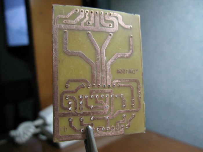
Etching the PCB, Diy pcb board
The etching process removes unwanted copper from the copper-clad board, leaving behind the traces of your circuit. This is typically done using an etching solution like ferric chloride, which chemically reacts with copper, dissolving it.
- Ferric Chloride: Ferric chloride is a common etching solution. It is relatively inexpensive and readily available. The etching process with ferric chloride can take some time, depending on the concentration of the solution and the temperature.
- Other Etching Solutions: Other etching solutions include copper chloride, ammonium persulfate, and sodium persulfate. These solutions may be more expensive or have different etching properties.
- Safety Precautions: Etching solutions are corrosive and can cause skin and eye irritation. Always wear protective gear, such as gloves, goggles, and a mask, when handling them. Work in a well-ventilated area.
Drilling Holes
Once the etching is complete, you need to drill holes for components and vias (connections between different layers of the PCB). This is done using a drill press or a hand drill with appropriate drill bits.
- Drill Bits: Use drill bits that are slightly smaller than the diameter of the holes you need.
- Drilling Technique: When drilling, apply gentle pressure and avoid pushing too hard. This will prevent the drill bit from breaking or damaging the PCB.
- Vias: Vias are holes that connect different layers of the PCB. They are typically drilled using a smaller drill bit than the components.
Testing and Debugging: Diy Pcb Board
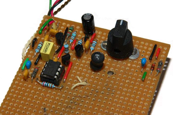
After you’ve assembled your DIY PCB board, the next step is to test its functionality and troubleshoot any issues that might arise. This process is crucial to ensure that your board works as intended and to identify any errors in your design or assembly.
Testing the PCB Board
Testing your PCB board involves verifying that all components are working correctly and that the connections between them are functioning as expected. This can be done through a series of tests, depending on the complexity of your project.
- Visual Inspection: Before powering up your board, it’s essential to perform a visual inspection. Look for any obvious errors like misplaced components, bent pins, or missing connections.
- Continuity Testing: Using a multimeter in continuity mode, check the connections between components. You can test if there is a complete path for current to flow between two points. If the multimeter beeps, it indicates continuity, meaning the connection is good. If it doesn’t beep, it might indicate a broken connection or an open circuit.
- Voltage Measurements: Use a multimeter to measure the voltage at different points on the board. Compare these measurements with the expected values to identify any voltage drops or inconsistencies.
- Functional Testing: Once you’ve confirmed the basic connections, you can test the functionality of the board by powering it up and observing its behavior. If your board includes LEDs, check if they light up as expected. If it includes a microcontroller, try running a simple program to test its functionality.
Troubleshooting Common Problems
If your PCB board doesn’t work as intended, you’ll need to troubleshoot the issue. Here are some common problems and tips for identifying them:
- Shorts: A short circuit occurs when two conductive paths come into contact unintentionally, creating an unintended pathway for current. This can be caused by solder bridges, misplaced components, or damaged traces.
- Open Circuits: An open circuit occurs when there is a break in the conductive path, preventing current from flowing. This can be caused by a broken trace, a loose connection, or a faulty component.
- Faulty Components: Components can fail for various reasons, including manufacturing defects, damage during assembly, or exceeding their operating parameters.
Using Multimeters and Oscilloscopes
Multimeters and oscilloscopes are essential tools for testing and debugging PCBs.
- Multimeters: Multimeters are versatile instruments used for measuring voltage, current, resistance, and continuity. They are essential for verifying power supply levels, checking for shorts and open circuits, and testing the functionality of components.
- Oscilloscope: Oscilloscopes are used for visualizing and analyzing electrical signals. They can display the waveform of a signal over time, allowing you to identify problems like signal distortion, timing issues, and noise. Oscilloscopes are particularly useful for debugging digital circuits and analyzing analog signals.
Debugging Techniques
- Divide and Conquer: When troubleshooting a complex circuit, it’s helpful to break it down into smaller sections and test each section individually. This allows you to isolate the problem area more quickly.
- Systematically Eliminate Possibilities: Start by checking the most likely causes of the problem and work your way through the list, eliminating possibilities as you go.
- Use Logic: When troubleshooting, it’s important to use logic and reasoning to understand how the circuit should work and identify any discrepancies.
- Document Your Findings: Keep a record of your testing steps and observations. This will help you track your progress and identify patterns in the problem.
Safety Precautions
Creating your own PCB boards is a rewarding experience, but it’s essential to prioritize safety throughout the process. Working with chemicals and electrical components requires careful attention to detail and adherence to proper safety procedures. This section will Artikel crucial safety precautions for each stage of the DIY PCB board creation process.
Working with Chemicals
Chemicals used in PCB board creation, such as etching solutions and cleaning agents, can be hazardous if not handled correctly. It’s vital to work in a well-ventilated area and wear appropriate personal protective equipment (PPE).
- Always wear safety goggles to protect your eyes from splashes and fumes.
- Use gloves to prevent skin contact with chemicals.
- Work in a well-ventilated area, preferably with a fume hood, to minimize exposure to harmful vapors.
- Store chemicals in their original containers, labeled with their proper names and hazards.
- Never mix chemicals unless you are sure of the resulting reaction.
- Dispose of chemicals properly according to local regulations.
Handling Electrical Components
Electrical components, especially those used in high-voltage circuits, can be dangerous if not handled carefully.
- Always disconnect power before working on any electrical circuit.
- Use insulated tools to handle electrical components, especially when working with high voltages.
- Be aware of the potential for static electricity discharge, which can damage sensitive components. Ground yourself by touching a grounded surface before handling delicate components.
- Never work on electrical circuits with wet hands or in damp environments.
Working with Tools
The tools used in PCB board creation, such as drills, soldering irons, and cutters, can pose risks if not handled properly.
- Always wear safety glasses to protect your eyes from flying debris.
- Use tools according to their intended purpose and manufacturers’ instructions.
- Keep tools sharp and in good working order.
- Store tools safely and out of reach of children.
General Safety Precautions
- Keep your workspace clean and organized.
- Be aware of your surroundings and avoid distractions.
- Take breaks to avoid fatigue.
- If you are unsure about any aspect of the process, consult a qualified professional.
Disposal of Hazardous Materials
Proper disposal of hazardous materials is crucial to protect the environment and human health.
- Dispose of chemicals according to local regulations. Never pour chemicals down the drain or into the garbage.
- Recycle or dispose of electronic waste properly.
- Use designated containers for hazardous waste.
- Consult with your local waste management authority for proper disposal procedures.
Embarking on the journey of DIY PCB boards opens a gateway to a world of innovation and personal fulfillment. With each project, you’ll gain valuable insights into electronics, refine your skills, and perhaps even discover new passions. Whether you’re a seasoned electronics enthusiast or just starting out, the world of DIY PCB boards awaits, offering a canvas for your creativity and a pathway to realizing your electronic dreams.
Designing your own PCB board can be a rewarding project, but it also requires a lot of planning and attention to detail. If you’re looking for a break from the technical side of things, why not take a look at some playground ideas DIY projects? They’re a fun and creative way to get your hands dirty and create something enjoyable for everyone.
Once you’ve had your fill of swings and slides, you can return to the world of circuit boards with a fresh perspective.

